|
Introduction:
|
The advent of electronic control meant that the operator no longer needed to be in the same
location as the dimmers. Control consoles can now be in the back of the house, while the dimmer
racks can be backstage, where wiring runs are shorter. This requires some form of communications
protocol – a digital "language," if you will, transmitted over a low-voltage cable,
or wirelessly – to allow the console to communicate with the dimmers. Prior to the 1990s, each
manufacturer used its own proprietary protocol; to use a controller from one company with dimmers
made by another usually required the use of converters. Common protocols included analog (usually
0-10V DC), AMX ("Analog Multi-pleX"),
and CMX ("Colortran Multi-pleX").
("Multiplexing" is the combining of several different message signals or data streams into one signal over a shared medium.)
This began to change with the introduction of the DMX512 standard (commonly referred to, across its
various revision levels, as "DMX", standing for "Digital
Multi-pleX"). For the first time, controllers
could work interchangeably, which made it practical to develop devices such as scrollers, moving lights,
LED fixtures, and other equipment which could now be
controlled by any console conforming to the professional standard. For purposes of this discussion, a
"device" is anything that has one or more attributes which can be controlled via a DMX signal. These
attributes might include intensity, color, movement...or almost
anything else you can imagine. Typical devices are moving lights, LED fixtures, scrollers, and, of course, dimmer racks.
|
|
History:
|
DMX512 was developed (built on CMX) by the United States Institute for Theatre Technology (USITT) in
1986. It was revised four years later. In 1998, the Entertainment Services and Technology
Association (ESTA) began to revise DMX512 as an ANSI standard. This revision, officially known as, "Entertainment Technology�USITT
DMX512-A�Asynchronous Serial Digital Data Transmission Standard for Controlling Lighting Equipment
and Accessories", was adopted by the American National Standards Institute in November of 2004 and
was revised again in 2008. It is the current standard, officially called, "E1.11 - 2008, USITT DMX512-A", or just
"DMX512-A".
|
|
Description and Limitations:
|
Each DMX network is referred to a "universe" and is limited to 512 discrete "addresses". Various
devices may use different numbers of addresses. A dimmer, for example, will typically use only one
address (so, a rack containing 192 dimmers would use 192 addresses), whereas a moving light might
use several dozen. When configuring a DMX-controlled device (and a dimmer rack is considered to be
a single "device"), it is necessary, usually, to set only the starting (lowest) address. This is done
from a menu or from switches. The addresses used by a DMX-controlled device are often referred to as
"DMX Channels." This should not be confused with the control channels on the lighting console (to read
more about the difference between "control channels" and "addresses", click here).
The device's "channel space" is the total number of DMX addresses it uses. For example, a typical LED
fixture might use the following configuration:
|
DMX Channel
|
Function
|
|
1
|
Intensity
|
|
2
|
Red
|
|
3
|
Green
|
|
4
|
Blue
|
|
5
|
Amber
|
So the fixture has a "channel space" of 5. If the starting address is 101, then it will use DMX addresses
101-105. A device may have several different operating modes, or "personalities," each of which will
use a different number of addresses.
Each universe may control up to 32 "unit loads". The unit load is a measure of how much power,
from the DMX run, is used by a device. Typically, each device will use one unit load.
If more than 32 unit loads are needed, the network can be
expanded by using an active DMX splitter/repeater (Note: This is not a "Y"-connector. There is, in DMX
cabling, no equivalent of the twofers used when cabling conventional fixtures with stage cable. Also note that the
splitter itself is a device and, as such, has a unit load).
Most DMX devices can be "daisy-chained"; they have a male connector for data input and a female connector for data
output. A cable can be run from this output to the next device in the chain. The cable run for a single
universe is limited to 1200 meters (approximately 3600'). Note that many manufacturers consider 1200
meters to be optimistic, and suggest using a repeater, to boost the signal, every 1000 feet.
Lighting consoles may control more than one universe.
The DMX standard calls for a 5-pin XLR connector or an 8-pin modular RJ45 connector. The protocol
itself uses only three conductors, the additional two wires being available for functions
proprietary to each manufacturer. Three-pin connectors are specifically prohibited by the standard,
but some companies ignore this and use 3-pin XLRs so as to allow the use of microphone cables.
Using mic cables is a very, very bad idea, for at least two reasons:
- Mic cables use different wire, with different electrical properties, than called for by the
DMX standard. This can cause signal degradation, exacerbated by the fact that the cable might
work fine...right up until the moment when it doesn't — usually in the middle of your
show's climatic scene.
- If a 3-pin DMX cable is accidentally plugged into an audio mixer furnishing phantom power,
the result can be unanticipated, and expensive, pyrotechnics.
Fortunately, 3-pin to 5-pin adaptors are fairly easy to rent, buy, or fabricate. For those so
inclined, the pinout is:
XLR: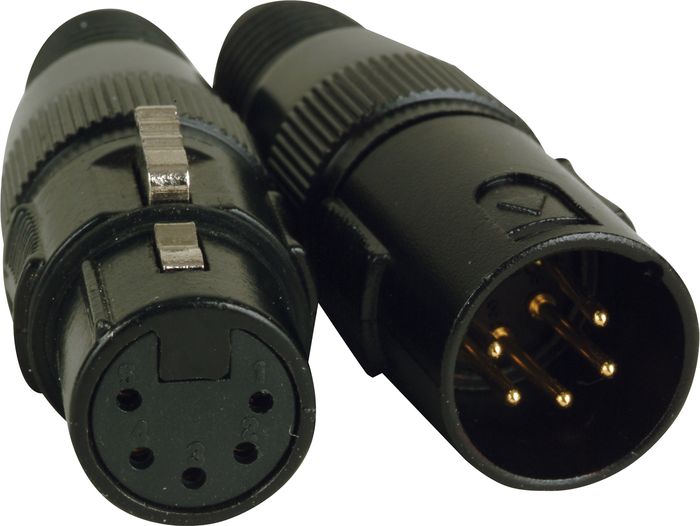
- Signal Common (the "shield")
- Data 1- (Primary Data Link)
- Data 1+ (Primary Data Link)
- Data 2- (Optional Secondary Data Link)
- Data 2+ (Optional Secondary Data Link)
RJ45:
- Data 1+ (White/Orange)
- Data 1- (Orange)
- Data 2+ (White/Green)
- Not Assigned
- Not Assigned
- Data 2- (Green)
- Signal Common (0 V) for Data 1 (White/Brown)
- Signal Common (0 V) for Data 2 (Brown)
On the 3-pin side of the adaptor, just ignore the Data 2 plus and minus. The Data 2 lines, being optional,
are often omitted even from 5-pin cables and theatre installations.
|
|
Recommended Practice:
|
- All runs should be properly terminated. See "Troubleshooting",
below.
- Use only CAT-5 wire or RS-485 rated wire.
- Do not run alongside power cables. When necessary for a DMX run to cross a stage cable, an extension cord,
or conduit, it should do so at a 90� angle. When necessary for it to be run parallel with a power cable, they
should be at least 6' apart. (Microphone cables also, should be kept away from power cables.)
- Speaking of microphone cable...don't use it. Even if mic cable looks similar to and uses the same connectors as
3-pin DMX cable, they are not the same. Annoyingly, mic cable might work perfectly... right up to the moment it
doesn't, and that moment always seems to be 30 minutes before the first performance.
|
Resolution
(8-Bit / 16-Bit)
|
You may occasionally see devices described as "8-bit" or "16-bit".
This refers to how the device receives information from the controller.
Even though most controllers are calibrated from 0-100, an 8-bit device, such
as a dimmer, receives its data in 256 steps (from "0" through "255"). This is called,
"8-bit," because in binary (the way computers handle numbers), the value 255 is expressed
as:
11111111
There are 8 digits (what, in your high school math class, you might have called, "places,").
In computer programming, these are called, "bits,", so..."8-bit".
When controlling incandescent fixtures, 8-bit resolution is perfectly adequate; the human eye cannot
really discern the difference between two adjacent steps and, as noted above, most controllers
only work with 100 steps anyway. The problem arises when one is working with LEDs and moving
lights which, when controlled with only 256 steps, have uneven fades or movements.
The solution is to use 16-bit resolution. This means that the device needs two DMX channels (since
each DMX channel can only resolve 256 steps). These are usually referred to as "coarse" and "fine".
For each change of one step in the coarse channel, the fine channel moves through all 256 of its possible
steps
For example, let's assume that we are fading an LED fixture from zero to full. At the beginning, both the
course and fine channels are at 0%. As we start the fadeup, the coarse channel stays at 0% and the fine
channel passes through all 256 of its steps. When the fine channel reaches its topmost level, it resets itself
to zero and the coarse channel moves from 0% to 1%. The process then repeats itself. This gives the device a
total of 65,536 (256 X 256) possible steps, resulting in much more delicate control.
In LEDs, the advantage of 16-bit resolution is the smoothness of the fade; 8-bit LEDs tend to flicker,
especially at lower intensities. With moving lights, 16-bit fixtures move more smoothly.
For example,  the Rosco I-Cue moving mirror, which is designed to fit in front of a conventional fixture, has both 8-bit
and 16-bit resolutions. The I-Cue has a maximum "pan" (That is, as you remember, the side-to-side movement)
of 230�. That means that each incremental change moves the mirror approximately 0.9�. That does not sound
like much, but at a 50' throw, the light will move 9" with every incremental change in level, making for very
choppy, unattractive movement. This is exacerbated by the fact that most controllers, as noted, work on a scale
of 0% to 100%. This means that an increase of 1% will actually change the DMX level by approximately two steps,
moving the I-Cue 18" at our 50' throw.
If, however, we change the resolution to 16-bit, the I-Cue, pans 230� in 65,536, not 256, steps. This means
that each incremental change moves the mirror only 0.0035�. This makes the movement on stage, even
at long throws, very subtle.
the Rosco I-Cue moving mirror, which is designed to fit in front of a conventional fixture, has both 8-bit
and 16-bit resolutions. The I-Cue has a maximum "pan" (That is, as you remember, the side-to-side movement)
of 230�. That means that each incremental change moves the mirror approximately 0.9�. That does not sound
like much, but at a 50' throw, the light will move 9" with every incremental change in level, making for very
choppy, unattractive movement. This is exacerbated by the fact that most controllers, as noted, work on a scale
of 0% to 100%. This means that an increase of 1% will actually change the DMX level by approximately two steps,
moving the I-Cue 18" at our 50' throw.
If, however, we change the resolution to 16-bit, the I-Cue, pans 230� in 65,536, not 256, steps. This means
that each incremental change moves the mirror only 0.0035�. This makes the movement on stage, even
at long throws, very subtle.
|
Troubleshooting:
|
DMX problems can be particularly irksome, and time-consuming, to troubleshoot. Providing a
comprehensive list of all possible problems and solutions is beyond the scope of this web site, but
here are some common issues:
- The device does not function at all.
- If no devices in that universe are working, then check the following:
- The outputs of the console may be incorrectly configured.
- You may have a bad DMX cable between the console and the first device in the DMX chain.
- There may be errors in patching (in the console) or the addressing of the device. Note that,
depending upon your console, a device with DMX address #001, connected to universe #2, might need to be
patched as address #513. The same device, connected to the third universe, would be addressed as #1025.
This is because the console treats the first universe as addresses 1 through 512, the second universe
as addresses 513 through 1024, the third universe as addresses 1025 through 1536, etc.
- If multiple subsequent devices in the DMX chain also are not working:
- There may be a bad cable between the last working unit and the first
non-functioning device.
- The last working unit may have a "Termination" switch set to the "On" position. Only the last
fixture in each chain should be terminated.
- Patching and addressing errors are also possible (they're always possible), but are less likely.
- The device functions, but incorrectly (For example, a command meant to pan a
moving mirror causes it to tilt instead).
- This is usually caused by the unit's being incorrectly addressed or patched.
- If the device has multiple operating modes, or "personalities", make sure the
correct one has been selected. Refer to the device's user manual.
- The device strobes and/or randomly flashes or moves. This is a very common issue, and the most cumbersome to fix. There
are two likely problems:
- Is the DMX cable run parallel with, and within 6" of, a power cable, conduit, or extension cord?
If so, move it farther away.
- You may have a bad cable. To troubleshoot this:
- Power down the devices for at least 30 seconds.
- Disconnect the DMX cable from the console to the first device, and
those between each device.
- Restore power.
- Reconnect the DMX cable from the console to the first device and then, one
by one, those between it and subsequent units in the chain. When the problem
resumes, you've found the bad cable.
- If your DMX run includes 3-pin cables, make sure that no mic cables have been used.
These problems are likely to affect fixtures both downstream and upstream
from the offending cable, so you will have to check every cable; you cannot
locate the problem merely by noting which is the first malfunctioning unit.
There are various meters available to test DMX cables, but please note that they
will not necessarily catch every defect.
- If the DMX run is long, you may have a termination issue. An unterminated run may result in
a shadow signal which bounces back through the run, causing unpredictable (but rarely desired) results. If the last device in the chain has a
termination switch, set it to "On"; otherwise, you will need to plug a DMX terminator into the
output of the last device in the run. These can be rented or purchased, or you can easily build
your own by soldering a 120 ohm resistor across the Data 1 plus and minus terminals.
It is good practice to terminate every run, no matter how short.
For a printable .PDF copy of this troubleshooting guide, click
here.
|
|
DMX References:
|
|
[Special thanks to Jerry Durand and David Fox.]
|