|
Scale:
|
Lighting graphics are said to be "drawn to scale". "Scale" is the relative size at which a
drawing is printed or plotted.
In American theatre (obviously, this may differ in countries that use the metric system),
the traditional scales are:
½" : 1'-0"
and
Ľ" : 1'-0".
If the scale is ½":1'-0", an object that is 1' long in the
"real world" is drawn ½" long on the drawing.
Likewise, if the scale is Ľ" : 1'-0", the same object would
be drawn Ľ" long.
In other words, a 3" line on the drawing represents a 12' wall in
the real world (because a 3" line is 12 quarters of an inch, and each
Ľ" represents one foot). These scales are generally
referred to as "quarter-inch" and "half-inch".
Resist whatever temptation you might have to
use other scales; in the American and Canadian professional theatre, electricians are accustomed to
these scales and using different ratios will cause confusion and waste of time.
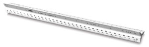 If you are reading a plot or drawing by hand, rather than with a Computer-Aided Drafting and Design (CADD) program, drawing and
measuring to scale is made much easier by using a special ruler called an "architects' scale"
(be aware that there is also a tool called an "engineers' scale", which uses the metric system but otherwise looks
exactly like an architect's scale).
If you are reading a plot or drawing by hand, rather than with a Computer-Aided Drafting and Design (CADD) program, drawing and
measuring to scale is made much easier by using a special ruler called an "architects' scale"
(be aware that there is also a tool called an "engineers' scale", which uses the metric system but otherwise looks
exactly like an architect's scale).
|
|
Plot:
|
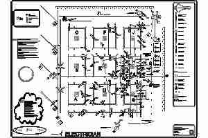
A "plan" drawing is an overhead view. A "composite" plan drawing is one that shows more than
one horizontal level. The light plot is a composite plan drawing that shows the type and
location of the lighting fixtures. It is used by the electricians when installing the production
— indeed, this phase of the process is often referred to as "hanging the plot". The plot may
consist of more than a single drawing, or "plate". When possible, the size and positions of
all hanging positions should
be drawn to scale, although it frequently becomes necessary (for reasons of space) to compress the
distance between Front-of-House positions and the stage. In these cases, the compression should be
clearly noted.
The light plot should include any information necessary for the electricians to have a clear
understanding of the designer’s intentions. The location and type of every fixture and accessory
should be indicated, along with the following information:
- The centerline. This line is drawn with alternating long and short dashes and should be
clearly labeled with a "CL" symbol.
- A lineset schedule (when appropriate).
- A ruler or some other indicator of distance left and right of centerline, in scale.
- A ruler indicating on-stage distances up and down stage, in scale.
- The edge of the stage, where applicable.
- The edge of the playing area, where applicable, especially when
it does not coincide with the edge of the stage.
- All scenic masking.
- All architectural and scenic obstructions.
- The proscenium arch, plaster line, smoke pockets, or other
architectural details necessary to orient the lighting design in flexible spaces.
- Trim (height) measurements for movable mounting positions
should read from the stage level surface (or other common
point of reference) to the pipe (or mounting position).
- Trim heights to boom positions measure from bottom of the boom base to the side arm or clamp.
- Identification (labeling) of hanging/mounting positions.
- The "legend" or instrument
key designating symbol type and notation in the light plot.
- The Title block.
- Sightlines.
The plot might also include such information as:
- Lighting areas.
- Revision date/number.
- Intended recipient ("Designer", "Electrician", "Archive", etc.).
- The basic scenic elements.
- Template key.
- Color key.
- Liability disclaimer.
- Union stamp.
The plot should always be clearly-drawn and easy to read.
|
Note that while the plot might be attractively drawn,
it is not the "lighting design". It is part of your art,
to be sure, but your real art, always, is the lighting itself, as
presented to the audience.
|
|
|
Section:
|
The section is a cross-sectional view in which the cutting plane intersects the space,
often through the centerline. In most cases, a composite section is appropriate, showing
all relevant architectural details from various planes, not just the centerline. The section provides information concerning the
relationship of the hanging positions to the architectural and scenic elements of the production.
Click on the image below to view a typical composite section.
 The section drawing should contain:
- A notation of the plane through which the section is “cut” (or, if appropriate, the descriptor,
"Composite").
- The "vertical zero" location — usually the stage floor
- The "horizontal zero" location — usually the proscenium, plaster line, or smoke pocket
- The upstage boundary of the performing space - usually the back wall or upstage-most backdrop
- Vertical audience sightlines
- Downstage edge of stage floor and/or edge of playing area
- Such architectural details as may affect the placement of lighting fixtures, including any obstructions.
- All hanging positions, including side elevations of vertical positions such as booms,
ladders, etc.
- Trim height for all hanging positions with adjustable height
- Identification of all lighting positions
- A sectional view of such scenery as may be relevant
- All masking
- Title block
- Scaled representation of the typical (or largest) fixtures that are to be hung on each position
- Human figure or other indication of head height
- Horizontal and vertical rulers in scale
- Defined distance to such other elements as may not be shown on the drawing, such as
follow spot positions, control booth, other sightlines, etc.
It may also contain:
- Liability disclaimer
- Union stamp
|
|
Title Block:
|
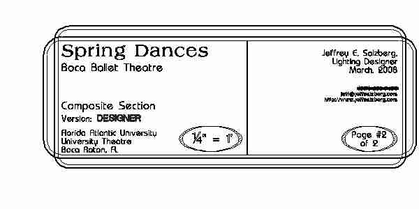
The title block is a box, located either in the bottom right corner of a drawing or as a vertical
banner along its right side. The title block should include the following information:
- Name of the producer or producing organization
- Name of the production
- Venue name and location
- Title of drawing (Such as "Light Plot" or "Composite Section")
- Drawing number (For example, "#1 of 2")
- Predominant scale of the drawing (Inset details may use a different scale, which
should be clearly indicated)
- Revision date
- Designer's name and title
- Draftsperson of the drawing
It may also include:
- Director's name
- Assistant Lighting Designer and/or Master Electrician
- Approval of the drawing
- Contact information such as telephone numbers and email addresses
|
|
Legend:
|
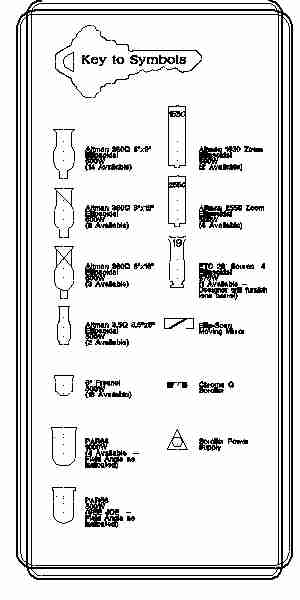 The legend or "key" is a representation and description of the symbols used in the plot. It may be
placed in any convenient location and should include:
The legend or "key" is a representation and description of the symbols used in the plot. It may be
placed in any convenient location and should include:
- Symbols of all fixtures and devices shown on the plot, with identifying descriptions
of each and, optionally, the available inventory
- Beam spread (in degrees or focal length) for each
fixture type if the numeric value is not part of the
fixture's name
- Wattage and/or ANSI lamp code
- Symbols for any accessories – templates, irises, color scrollers, top hats, barn doors, etc.
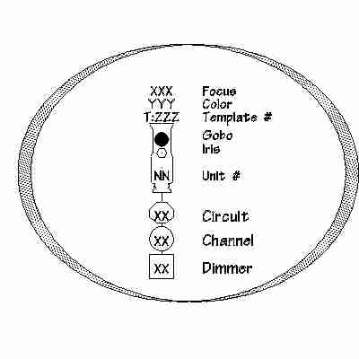
- The following information may be included in the legend or may be in a separate box (see image below):
- Designation of all notations (such as channel, dimmer, circuit, color,
template) associated with each fixture.
- Color manufacturer designation (e.g., R = Rosco, L = Lee, G = Gam, etc.)
- Template manufacturer designation (when applicable)
- The legend should be enclosed in a box so that it is completely clear
to the electricians that the
fixtures contained therein are not to be hung as part of the plot.
Click on the image to the right to view an example of a legend.
|
|
Numbering:
|
|
Hanging Positions:
|
Positions which intersect centerline (in other words, usually, which run from SL to SR)
are numbered from the proscenium outward (in the
case, of course, of a proscenium stage). For example:
- Front of House (FOH) positions are numbered or labeled from the position closest to the proscenium and progressing to the position farthest from the proscenium.
- Onstage electrics are numbered from downstage to upstage.
- Onstage booms are numbered from downstage to upstage.
- Box booms, booms, and other positions which do not intersect centerline are divided between
stage left and stage right, with stage left listed first.
For examples of ways to number the hanging positions in a non-proscenium stage,
click on these images:
In general, when numbering the positions in a non-proscenium space, or a proscenium space
with an overhead pipe grid instead of conventional battens:
- Pipe grid positions should be designated by numbers on one axis of the grid and
by letters on the other axis (See the example on the above right).
- Other unconventional mounting positions may be designated by compass points or numbering in a clockwise manner.
- As in the left-hand example above, grids with discrete "cells" or "bays" may have each such lettered or
numbered.
|
|
Fixtures:
|
Each instrument receives a unique whole number. If a fixture has
an accessory that alters the beam of an instrument, the accessory may or may not receive its
own number (a good rule of thumb is that if the accessory requires its own power source
or control channel [for example, color scrollers and automated irises], it should be numbered
discretely). When fixtures are inserted between previously numbered fixtures, they are
given the lower-numbered fixture's unit number with an additional
letter (for example, "12a" or "36b"). Fixtures with multiple circuits, such
as striplights and cyclorama lights, are assigned a letter with a corresponding
number for each circuit (for example, "A1", "A2" and "A3" might be the numbers of a three-circuit
striplight), while fixtures needing multiple control channels or attributes (such as moving lights
or LED fixtures) are numbered with a whole number followed by a decimal point and number for each
attribute (for example, if unit #24 is an LED fixture, "24.1" might be the red circuit, "24.2"
might be the green circuit, "24.3" might be the blue circuit, etc.).
In general:
- Units mounted on hanging positions which are perpendicular to
centerline (for example, overhead pipes or most FOH positions) are numbered from stage left
to stage right.
- Units mounted on vertical hanging positions such as onstage booms or ladders are numbered
from top to bottom, downstage to upstage.
- Fixtures mounted on FOH positions which are parallel to centerline should be numbered
beginning with the units nearest to plaster line.
|
|
Channel Assignment:
|
Assigning channels is, as much as anything, a matter of personal
preference and convenience. You can, of course, just start with Channel #1 and number everything
sequentially, but you may find it more convenient, in tech rehearsals, to "bundle" washes
(and other channels which might all work together) so that each one starts with a "1",
as in this example:
|
Wash
|
Channel #s
|
|
Cool Fronts
|
Channels 1-14
|
|
Warm Fronts
|
Channels 21-34
|
|
Cool Sides
|
Channels 41-48
|
|
Throne Special (Front)
|
Channel 51
|
|
Throne Special (Sides)
|
Channel 52
|
|
Throne Special (Back)
|
Channel 53
|
The important thing to remember is that channel assignment should be done in
such a way as to be most convenient for you and the board operator.
|
|
|
Symbols:
|
Some guidelines to remember when drawing fixtures:
- The fixture symbols used on the light plot should approximate the scale size and shape
of the fixtures and should be placed so that their locations reflect the fixtures' exact hanging
points.
- Unless otherwise noted, the default spacing between typical fixed focus fixtures should be
18”, to allow sufficient clearance for focusing each unit.
- When symbols are placed with spacing other than the default 18", dimension lines or other
measuring notations should be added between the symbols to indicate the distance.
- The fixtures may be drawn so as to face their focus points, or on 90° axes.
Normally, each symbol is accompanied by the following information:
- Fixture number
- Indication of focal length or beam spread as part of the symbol (where appropriate)
- Indication of any accessories such as templates, irises, scrollers, top hats, barn doors, etc.
- Channel (or control designation), drawn inside a circle
- Axis notation for PAR lamps (which, remember, are usually oval-shaped)
Additional information may include:
- Focus (The point to which the fixture is to be aimed)
- Wattage
- Dimmer (drawn inside a square or rectangle) and/or circuit (drawn inside a hexagon) number (or space for the electrician to add this information during the hang)
- Indication of twofers
- Color notation
- Color notation for scrollers
- Template notation
Note that if the plot is overly busy and difficult to read, some of the above information may be
omitted for the sake of clarity, but it should always be included in the instrument schedule, channel
hookup, and other paperwork.
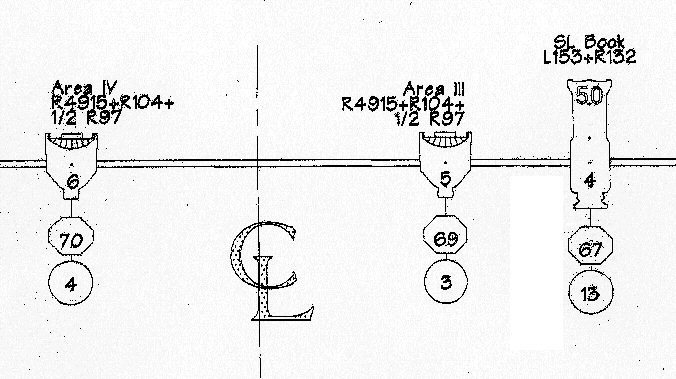
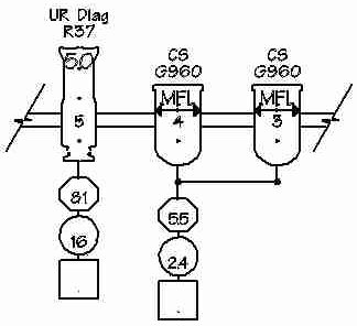 In the image to the right, fixtures #3 and #4 are twofered, as evidenced by the right-angled lines
(with the dots in the corners, to indicate the legs of the twofer) linking them.
They are Medium-FLood PAR56s
(as indicated by the "MFL" in each fixture's nose), and are pointed center-stage, with their oval beams
turned horizontally (note the double-headed arrows in the fixture noses). They are both colored with
GAM960 and are plugged into circuit 55, and will be controlled by channel 24. The box for the dimmer
information has been left blank for the electrician or assistant lighting designer to fill in at a
later date.
In the image to the right, fixtures #3 and #4 are twofered, as evidenced by the right-angled lines
(with the dots in the corners, to indicate the legs of the twofer) linking them.
They are Medium-FLood PAR56s
(as indicated by the "MFL" in each fixture's nose), and are pointed center-stage, with their oval beams
turned horizontally (note the double-headed arrows in the fixture noses). They are both colored with
GAM960 and are plugged into circuit 55, and will be controlled by channel 24. The box for the dimmer
information has been left blank for the electrician or assistant lighting designer to fill in at a
later date.
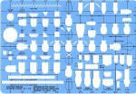 When drafting by hand, as with the architects' scale mentioned above, there are specialized drafting
tools, called "templates" that greatly simplify the drawing of symbols.
When drafting by hand, as with the architects' scale mentioned above, there are specialized drafting
tools, called "templates" that greatly simplify the drawing of symbols.
Examples of the most commonly-used lighting symbols can be downloaded from Jeffrey E. Salzberg's
web site.
|
|