Computer Aided
Drafting and Design
has, for the most part, replaced manual drafting, especially in
the area of theatrical design. Some of the advantages of CADD are:
- CADD, once the user masters the program, is much faster
than is drafting by hand. In addition, many repetitive
tasks can be automated, and if a designer does multiple
productions in the same theater(s), the building does
not need to be redrawn every time..
- Keeping archival copies of your work in electronic form
takes up much less physical storage space than does
keeping copies on paper.
- Sending drawings to clients and collaborating with fellow
designers is faster by email than by postal mail.
- When manually drafting a plot, you are limited to those symbols
which happen to have been included on the commercial template (stencil) you've purchased; when using
CADD, you can design any symbol or block you need.
There are several different CADD packages available. The most
popular amongst theatrical lighting designers is Vectorworks,
which comes with several features specifically geared toward
stage lighting, including the ability to automatically generate the paperwork.
Also popular is Autocad. Jeff uses Visual CADD,
which is comparatively less expensive, and easy to learn. The
tutorial below is based upon Draftsight, which is free and available
for a number of different operating systems.
|
|
Install and Configure Draftsight®:
|
This tutorial was developed for the TH341 Lighting Design class
at Saint Michael's College, in Colchester, VT, and is based upon
Draftsight, a CADD program developed by Dassault Systčmes.
Draftsight is available for Windows, Mac OS X, and a variety
of Linux distributions. It is free (although registration/validation
is required) and can be downloaded from
http://www.3ds.com/products/draftsight/download-draftsight/
The purpose of this tutorial is not to teach
you everything you need to know in order to draft a light plot
from scratch; its purpose is to give you a broad overview of
the way CADD programs function, and the things you can do with
them, and to prepare you for future learning, either in a
classroom or autodidactically.
Note that, while the concepts are the same, the vocabulary and
precise functionality will differ between CADD platforms.
After downloading and installing the program, run it and click
"Help" and then, from the drop down menu,
Click on "Help..." again. Click "The User Interface" and
familiarize yourself with the Draftsight
screen.
When ready, close the "Help" window.
Draftsight's default colors are white on black, which some people
find hard on the eyes, so let's fix that now.
|
On a PC:
|
- Click "Tools".
- Then click "Options".
- When the "Options" window opens, click
"System Options" from the menu on the left.
- Click the "+" next to
"Display" and then the "+" next to "Element Colors".
- Set the "Model Background" to white.
- Now, if there is a
"+" next to "Screen Options", click it. Make sure the
checkbox next to "Show scroll bars" is checked, and
then click "OK".
|
|
On a Mac:
|
- Click "Draftsight".
- Then click "Preferences".
- Click
"System Options" from the menu on the left.
- Click the arrow next to "Display"
- Click the arrow next to "Element Colors".
- Set the "Model Background" to white.
- Now click on the arrow next to "Screen Options". Make sure the
checkbox next to "Show scroll bars" is checked, and
then click "OK".
|
If you have not yet done so,
you will find it helpful to have read the
CADD Glossary
before proceeding.
|
|
Load Sample Drawing File:
|
Now, in your web browser, download the
sample CADD drawing we'll be using for this project. Save
it to a folder on your hard drive or network.
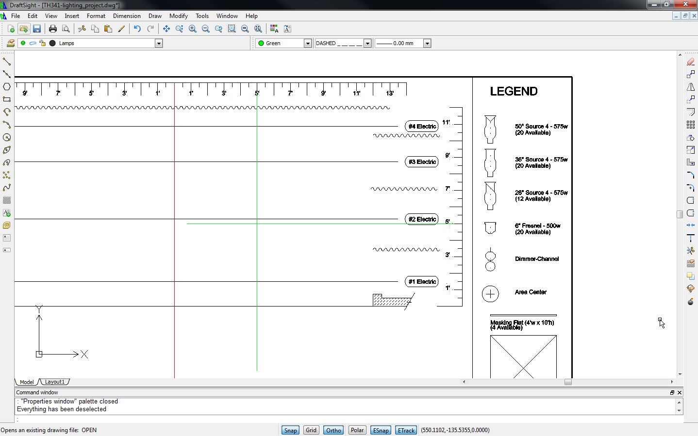
Return to Draftsight, and load the sample file. It should look
like this:
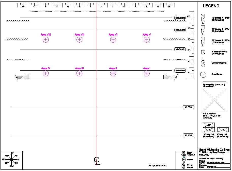 If it doesn't look like that, click "View" > "Zoom" > "Fit".
|
|
Zooming:
|
You can zoom in to get a closer view of one part of
your drawing:
- Click "View" > "Zoom" > "Window".
- In the drawing space, click in the area that
is at the top left of the part of the
drawing you wish to see in more detail.
- Drag the mouse cursor to the bottom right of
the area to which you wish to zoom. Click.
- Click "View" > "Zoom" > "Fit".
If your mouse allows it, you can also use the scroll
wheel to zoom in and out dynamically.
|
|
Snaps
|
Before we proceed, we need to set our snaps. If you don't remember what
snaps are, check the CADD Glossary.
|
On a PC:
|
- Click "Tools" > "Options".
- Click "User Preferences".
- Expand "DraftingOptions" > "Pointer Control" > "Entity Snaps".
|
|
On a Mac:
|
- Click "Draftsight" > "Preferences".
- "User Preferences" (on the left-hand menu).
- Expand "DraftingOptions" > "Pointer Control" > "Entity Snaps".
|
Under "Geometry ESnaps", make sure the following are checked:
- Nearest
- End
- Midpoint
- Center
- Insert
Under "Reference ESnaps", make sure "Intersection" is checked.
In both columns, uncheck all other options. Click "OK".
As you become more familiar with the program
you should feel free to reconsider these options to fit your own style.
|
|
Working with Layers:
|
You will have noticed two rows of pink blocks labeled
as areas 1-8. These will be useful later in the
tutorial, but for now, they are in the way.
These blocks are on a layer titled "Area Centers".
Individual layers can be manipulated in a number of
ways:
- They can be given
default colors and default line types.
- They can be "locked"
so as not to be changed by accident.
- They can be hidden or made visible.
For now, let's hide the "Area Centers" layer.
- Click "Format" > "Layer..."
- The "Layer Manager" box will appear.
- Note that the "Area Centers" layer has a green dot
under the column labeled "Show". Click this dot. It will turn gray.
- Click "OK". The area center symbols and labels
will disappear.
|
|
Working with Text:
|
Now let's enter some text. Use the "Zoom Window" or
"Zoom In" functions to zoom into the title block at
the bottom right of the drawing area. Now your screen
should look something like this:
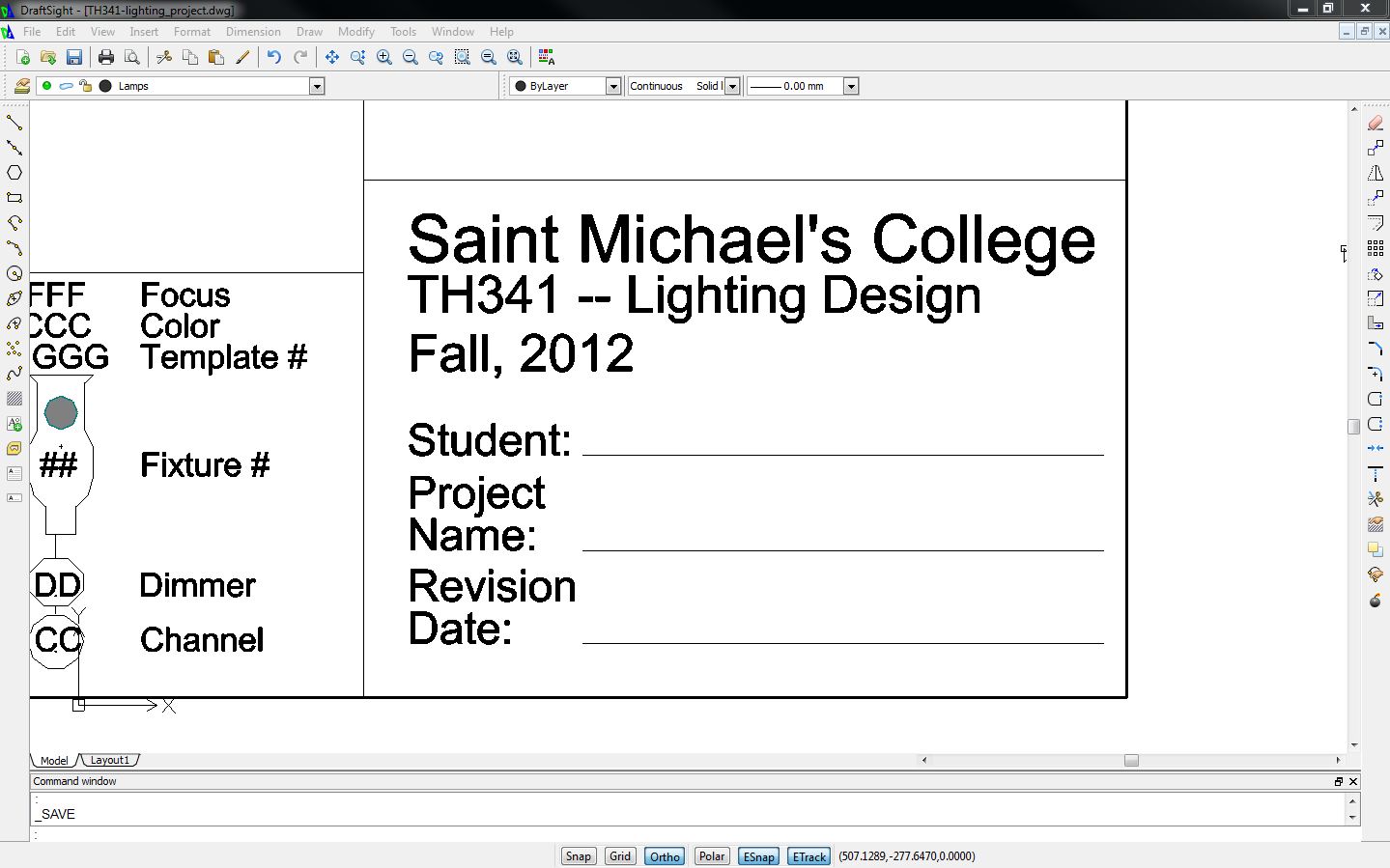 Click "Draw" > "Text" > "SimpleNote".
The "Insert SimpleNote" box will appear. Type your
name in the "Text" box. Make sure the "Select in
Graphics Area" box (underneath "Insertion Point") is
checked. Make sure that "Left" (under "Insertion
Orientation" is also selected. Under "Options",
set your height to 3.0 inches.
Click "OK".
Your name will appear on the screen, attached to the
mouse cursor. Hover the mouse cursor over the left
end of the line after "Student". After a few
seconds, the words "End point" will appear. Click.
Now do the same with the name of your project (for
now, you can make one up; it's easy to change later).
Now let's enter the date. This involves a couple of
extra steps. As before, Click "Draw" > "Text" > "SimpleNote",
but, instead of entering text, click the "Field" button
(It looks like this:
Click "Draw" > "Text" > "SimpleNote".
The "Insert SimpleNote" box will appear. Type your
name in the "Text" box. Make sure the "Select in
Graphics Area" box (underneath "Insertion Point") is
checked. Make sure that "Left" (under "Insertion
Orientation" is also selected. Under "Options",
set your height to 3.0 inches.
Click "OK".
Your name will appear on the screen, attached to the
mouse cursor. Hover the mouse cursor over the left
end of the line after "Student". After a few
seconds, the words "End point" will appear. Click.
Now do the same with the name of your project (for
now, you can make one up; it's easy to change later).
Now let's enter the date. This involves a couple of
extra steps. As before, Click "Draw" > "Text" > "SimpleNote",
but, instead of entering text, click the "Field" button
(It looks like this:  )
Using the "Category" pulldown menu, select "Date and Time",
and, using the "Name" pulldown menu, select "Date".
Click "OK" and you will see the current date appear in
the "Text" box. Click "OK" again, and position the date
appropriately, as you did with your name and show title.
Your title block should now look much like this: )
Using the "Category" pulldown menu, select "Date and Time",
and, using the "Name" pulldown menu, select "Date".
Click "OK" and you will see the current date appear in
the "Text" box. Click "OK" again, and position the date
appropriately, as you did with your name and show title.
Your title block should now look much like this:
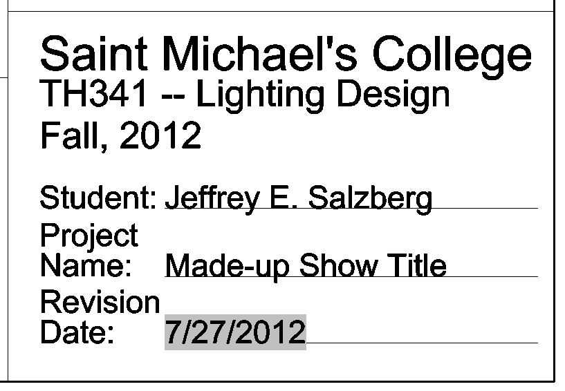 Speaking of the show title, let's change it to the
title of a real show. Hover the mouse over the text, and click.
The text is now selected. Right click and select "Edit".
Type the "real" name of the show and click "OK". The
show name will change on the screen.
Note: If you accidentally select the wrong object, you can
release it by right-clicking and choosing "Deselect All".
The "Edit" function is what's called a "persistent"
command. This means that you will stay in "edit" mode
until you manually cancel it (Click on your name, now.
The edit box will appear. Click on "cancel".) You can get out of "edit"
mode either by pressing [ESCAPE] or by right-clicking and selecting "Cancel".
Speaking of the show title, let's change it to the
title of a real show. Hover the mouse over the text, and click.
The text is now selected. Right click and select "Edit".
Type the "real" name of the show and click "OK". The
show name will change on the screen.
Note: If you accidentally select the wrong object, you can
release it by right-clicking and choosing "Deselect All".
The "Edit" function is what's called a "persistent"
command. This means that you will stay in "edit" mode
until you manually cancel it (Click on your name, now.
The edit box will appear. Click on "cancel".) You can get out of "edit"
mode either by pressing [ESCAPE] or by right-clicking and selecting "Cancel".
|
|
Working with Blocks:
|
An important part of lighting design is the way the lighting interacts with the scenery,
so let's plot a basic ground plan.
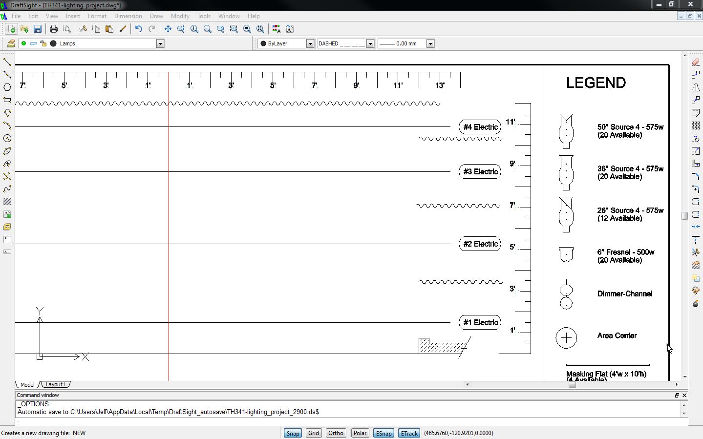
First, zoom in to the SL half of the stage, including the rulers at
the top and side of the stage. Your screen should look somewhat like this:
 At the bottom of your screen, make sure "Ortho" is selected, and
then look at the property bar at the top of your screen:
At the bottom of your screen, make sure "Ortho" is selected, and
then look at the property bar at the top of your screen:
 Click on the "Color" dropdown menu and change the color to Green.
Change the layer from "Lamps" to "Set".
Now click "Draw" > "Line" (or select the "Line" tool from the toolbar on the left
side of your screen). Hover over the ruler line (on the top ruler) which indices 5' SL until "End point"
appears. Left click and then drag the mouse straight down. Click. Press [ESCAPE].
Now, select the "Line" tool again and draw a horizontal line 5' US of the proscenium arch.
Now your screen should look like this:
Click on the "Color" dropdown menu and change the color to Green.
Change the layer from "Lamps" to "Set".
Now click "Draw" > "Line" (or select the "Line" tool from the toolbar on the left
side of your screen). Hover over the ruler line (on the top ruler) which indices 5' SL until "End point"
appears. Left click and then drag the mouse straight down. Click. Press [ESCAPE].
Now, select the "Line" tool again and draw a horizontal line 5' US of the proscenium arch.
Now your screen should look like this:
 Reset the color to "ByLayer".
Click "Insert" > "Block..." The "Insert Block" box will appear (imagine that!).
In the "Name" dropdown menu, select "platform-16 in". Make sure the "Specify later" box
under "Position" is checked, and that none of the other "Specify later" boxes are checked.
Set the "Rotate" angle to 30. Click "OK".
Hover your mouse cursor over the intersection of the two green lines until "Intersection"
appears, then click.
Again click "Insert" > "Block...", but this time select "platform-8 in".
Set the "Rotate" angle to 210. Click "OK".
Hover your mouse cursor over the SR-most corner of the 16" platform until "End point"
appears, then click.
Click on each of the green lines to highlight them, and press [DELETE]. Your screen should
look like this:
Reset the color to "ByLayer".
Click "Insert" > "Block..." The "Insert Block" box will appear (imagine that!).
In the "Name" dropdown menu, select "platform-16 in". Make sure the "Specify later" box
under "Position" is checked, and that none of the other "Specify later" boxes are checked.
Set the "Rotate" angle to 30. Click "OK".
Hover your mouse cursor over the intersection of the two green lines until "Intersection"
appears, then click.
Again click "Insert" > "Block...", but this time select "platform-8 in".
Set the "Rotate" angle to 210. Click "OK".
Hover your mouse cursor over the SR-most corner of the 16" platform until "End point"
appears, then click.
Click on each of the green lines to highlight them, and press [DELETE]. Your screen should
look like this:
 Now we have a set to light.
The blocks included with this drawing are not "off-the-shelf"
features of Draftsight; they were specifically created for this project.
In the future, we will be adding a "Creating Blocks" section to this tutorial,
but in the meantime, if you should feel the need to create your own blocks,
see "Defining Blocks" in the Draftsight help file.
Now we have a set to light.
The blocks included with this drawing are not "off-the-shelf"
features of Draftsight; they were specifically created for this project.
In the future, we will be adding a "Creating Blocks" section to this tutorial,
but in the meantime, if you should feel the need to create your own blocks,
see "Defining Blocks" in the Draftsight help file.
|
|
Cartesian Coordinates:
|
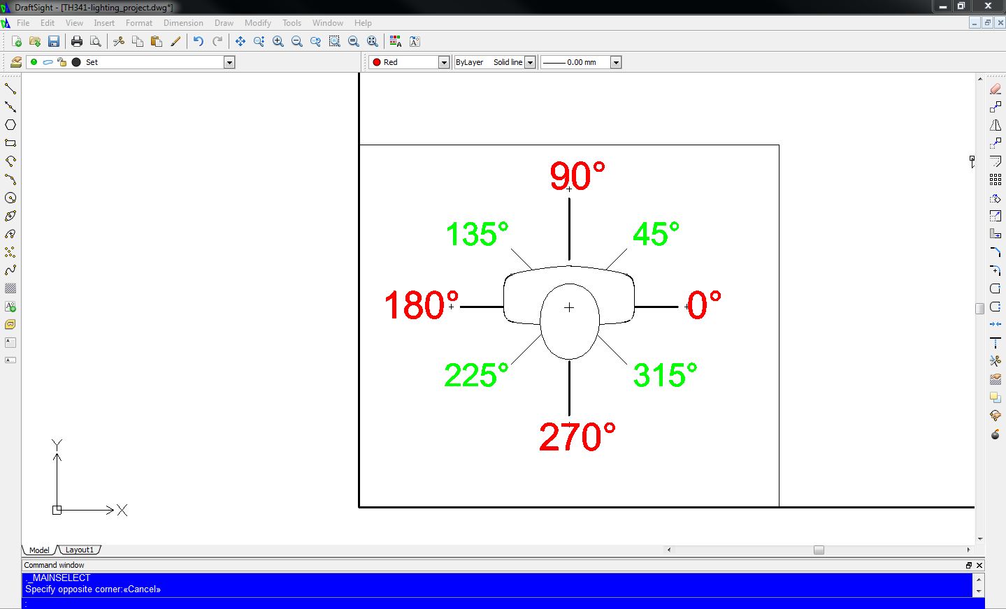
You might have noticed the compass at the lower left of the drawing, as
well as the arrows labeled "X" and "Y", which persist at the lower left
of your screen:
 In order to create an accurate drawing, we must have a system for precisely
placing objects on the page. Two-dimensional CADD programs use Cartesian Coordinates
and Polar Coordinates.
Imagine a piece of graph paper with a line dividing it in half horizontally and
another dividing it vertically. These lines are axes ("AK-seez") Using Cartesian Coordinates,
you can accurately and reproducibly plot any point based on its distance from each axis. It works like this:
In order to create an accurate drawing, we must have a system for precisely
placing objects on the page. Two-dimensional CADD programs use Cartesian Coordinates
and Polar Coordinates.
Imagine a piece of graph paper with a line dividing it in half horizontally and
another dividing it vertically. These lines are axes ("AK-seez") Using Cartesian Coordinates,
you can accurately and reproducibly plot any point based on its distance from each axis. It works like this:
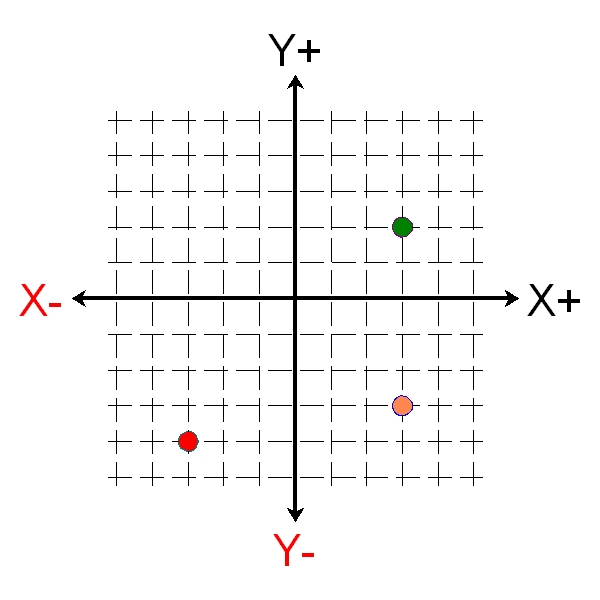 The horizontal axis is called the "X" axis, with "0" being the point at which it intersects the vertical
axis. The values increase as you go to the right and decrease as you go to the left. The "Y" axis is the
vertical, with its "zero" point at its intersection with "X". The "Y" axis' values increase as you go up
and decrease as you go down. A mnemonic to help you remember which axis is which is that an "X" is
a "cross", and the "X" axis goes "across" the screen.
The coordinates are always written in alphabetical order and separated by a comma:
x,y
...So, "0,0" would be the intersection of the two axes. A point at "2,3" would be 2 units to the left
and 3 units up. In the above drawing, the green dot is at "3,2", the red dot is at "-3,-4", and the
amber dot is at "3,-3".
The horizontal axis is called the "X" axis, with "0" being the point at which it intersects the vertical
axis. The values increase as you go to the right and decrease as you go to the left. The "Y" axis is the
vertical, with its "zero" point at its intersection with "X". The "Y" axis' values increase as you go up
and decrease as you go down. A mnemonic to help you remember which axis is which is that an "X" is
a "cross", and the "X" axis goes "across" the screen.
The coordinates are always written in alphabetical order and separated by a comma:
x,y
...So, "0,0" would be the intersection of the two axes. A point at "2,3" would be 2 units to the left
and 3 units up. In the above drawing, the green dot is at "3,2", the red dot is at "-3,-4", and the
amber dot is at "3,-3".
|
|
Polar Coordinates:
|
With Cartesian Coordinates, you place a point according
to its absolute "X" and "Y" values. Polar Coordinates
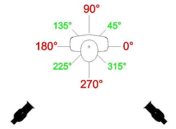
are used to place a point relative to another point. Remember the compass?
As you can see, based on the way the little actor is facing, 0° is toward SL, 90° is toward
US, 180° is toward SL, and 270° is toward DS. Let's say that we want a backlight to hit the
actor from over his right shoulder.
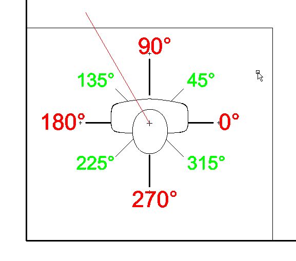
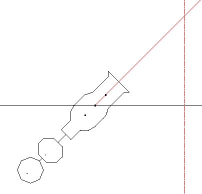
- On the toolbar at the top of the drawing area, change the line color
to red (This is just to make it easier to see).
- Zoom in to the compass.
- Click "Draw" > "Line" (or choose the "Line" tool from the toolbar on the
right).
- Hover over the intersection of the two crossed lines in the
middle of the actor's head, until "Midpoint" appears. Click.
- Type "@2'<120" and press [RETURN] [ESCAPE]. Your drawing should now look
somewhat like this:
|
|
Choosing Fixtures:
|
What does this have to do with drafting a light plot? Let's see.
(This is about to get complicated. Hang in there.)
For the sake of this exercise, let's assume that we want to light the actors with McCandless
angles (one light from 45° SR and another coming from 45° SL). Since the actors, when facing downstage,
are facing toward 270° (remember the compass), we'll be using 225° for our stage right angle (because that's 45°
subtracted from 270°) and 315° for our stage left angle (because that's 270° plus 45°).
 Zoom out to see the entire drawing (One way to do this is to press "View" > "Zoom" > "Fit"). If you do not see the 8
pink Area Center symbols, that means that the "Area Centers" layer is hidden. You can reveal it by clicking "Format > Layer"
and clicking on the gray dot at the intersection of the row labeled "Area Centers" and the column marked "Show". Now zoom
in on the symbol for Area I. Let's draw a line from the center of that area to the #2 FOH
hanging position:
Zoom out to see the entire drawing (One way to do this is to press "View" > "Zoom" > "Fit"). If you do not see the 8
pink Area Center symbols, that means that the "Area Centers" layer is hidden. You can reveal it by clicking "Format > Layer"
and clicking on the gray dot at the intersection of the row labeled "Area Centers" and the column marked "Show". Now zoom
in on the symbol for Area I. Let's draw a line from the center of that area to the #2 FOH
hanging position:
- Select the "Line" tool.
- Hover over the intersection of the lines in the center of the "Area II" symbol until "Midpoint" appears. Click.
- Type "@16'<315".
- You have just drawn a 16' line indicating the axis of a beam of light hitting the actor from
the #2 FOH at an angle of 45° from SL.
- For the next step, it will be helpful to know the exact distance from the light to the center of the area.
- Zoom in on the place where the line you just drew intersects the #2FOH.
- Type "trim" [RETURN]
- The command line prompt will say, "Specify cutting edges." Click on the #2FOH and press [RETURN].
- Now the command line says, "Specify segments to remove". Click on the part of the diagonal line that is DS
of the #2FOH.
- Press [ESCAPE]. You have just learned how to trim a line to its intersection with another object.
- Click on the diagonal line to highlight it.
- Right click and choose "Properties".
- When the "Properties" box appears, look at the very bottom field.
This tells you the length of the selected object, which in this case is just over 15'-6".
- Leftclick and choose "Deselect All".
Now we know where we want to put our first fixture, but we have to decide which fixture to use.
Before we can do that, we have to know what the throw is.
"Wait!" I hear you say. "Didn't we just do that? Isn't the throw 15'-6"?"
Well...no. 15'-6" is the distance from the actor's head to a spot right under the
place where the fixture will be hung. Look at this graphic:
 So, it's really just a right triangle, and the Pythagorean Theory tells us that the hypotenuse (the throw
squared is equal to the squares of the two sides (the height and the 15'-6" distance to the actor).
As noted on the CADD drawing, the pipe trims (in other words, the height of the pipes on which we're
hanging lights) are all 17'-1", putting the fixtures themselves at 16'-0" — exactly 10'-0" higher than the head
of a 6' tall actor. This means that we can calculate the throw thusly:
Throw2 = 100 X 240.25
. . .or. . . .
Throw2 = 340.25
. . .or. . . .
Throw = √340.25
. . .or. . . .
18.44
Now zoom in to the legend, at the top right of the drawing, where you'll
see the fixtures available to you for this project, with the maximum quantities of
each.
As you remember from the Photometrics section, we compute the field size by multiplying the
throw by the multiplication factor. Here are the factors and the
peak candela (we'll need this in a minute) for
the four types of fixtures available for this project:
So, it's really just a right triangle, and the Pythagorean Theory tells us that the hypotenuse (the throw
squared is equal to the squares of the two sides (the height and the 15'-6" distance to the actor).
As noted on the CADD drawing, the pipe trims (in other words, the height of the pipes on which we're
hanging lights) are all 17'-1", putting the fixtures themselves at 16'-0" — exactly 10'-0" higher than the head
of a 6' tall actor. This means that we can calculate the throw thusly:
Throw2 = 100 X 240.25
. . .or. . . .
Throw2 = 340.25
. . .or. . . .
Throw = √340.25
. . .or. . . .
18.44
Now zoom in to the legend, at the top right of the drawing, where you'll
see the fixtures available to you for this project, with the maximum quantities of
each.
As you remember from the Photometrics section, we compute the field size by multiplying the
throw by the multiplication factor. Here are the factors and the
peak candela (we'll need this in a minute) for
the four types of fixtures available for this project:
|
Fixture
|
M.F.
|
Peak
Candela
|
|
50° Source Four
|
0.93
|
34,900
|
|
36° Source Four
|
0.65
|
82,000
|
|
26° Source Four
|
0.46
|
159,000
|
|
6" Fresnel (Spot)
|
0.28
|
92,500
|
|
6" Fresnel (Flood)
|
1.4
|
8,800
|
So if our throw is 18' (it's OK to round down), the field size of a 26° Source Four
is:
18 X 0.46
. . .or approximately 8'-4".
On our sample drawing, the area centers are 6' apart (If you are doing this as part of
a classroom assignment, you should feel free to change this to fit your needs -- pending
approval from your instructor, of course). With a 26° fixture, we would have only 1' of
overlap on each side — probably not enough to ensure a smooth transition as the actor
crosses from one area to the other (2' is a useful minimum). We should look at a fixture with a wider field,
The 50° Source 4 has a 0.93 multiplication factor, so at our 18' throw, it has a 16'-9" field.
This is certainly big enough — too big, in fact, as it is over twice the size of our target
area — but will it be bright enough? Remember that the wider a fixture's field, the dimmer
it becomes. As discussed in the Photometrics section, the formula for computing a fixture's
intensity at a given throw is:
[Peak Candela] / [Throw2] = [Footcandles]
Using this formula, we find that the intensity is 107 footcandles. This is marginal; 150 is a good minimum, as a
rule of thumb. We could change to 3-8' areas, or even 2-12' areas, and use the 50° units, but we'd have to accept
the lower intensity, and we might need those fixtures for washes and specials over the stage, where throws are
likely to be shorter. Let's see what the 36° Source Fours will do for us.
The 36° unit has a multiplication factor of 0.65 and a peak candela of 82,000. Using these numbers,
we come up with a field size of approximately 11'-6" (giving us almost 3' of overlap on each side)
and an intensity of 253 footcandles. I do believe we've got a winner!
|
|
Determining the Vertical Angle:
|
Now we know where on the pipe we want to place our first fixture, but will it strike the actor
at the appropriate angle? Will it be too high? Too low? Will Goldilocks find true love?
While Dr. McCandless, in addition to writing that the optimum horizontal angle is
45°, wrote that the preferred vertical angle is also 45°, in practice you will find that vertical
angles of anywhere between 30° and 45° are acceptable, depending on how "flat" you want the
performers to look, and of course, the architecture of the building.
Let's see if our proposed hanging position falls within that range. In your web browser, download
TH341-computing_throw.dwg and open it with Draftsight.
If necessary, click "View" > "Zoom" > "Fit".
You'll notice that it's the same drawing we looked at, above, when we were computing the throw.
- Click "Dimension" > "Angular".
- Hover over the line indicating the throw until it's highlighted, and then click.
- Hover over the horizontal line labeled "15'-6" and click.
- An arc with the angular dimension will appear. If it should above or below the two
lines with which we are working, move your mouse cursor until it is between the two lines. Your drawing
should now look something like this:
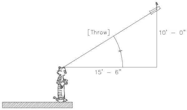
As you can see (although you might have to zoom in to do so) the angle is 32°. This might be a little "flat"
for some shows, but it's within our target range (even if barely so) and for this exercise, 'twill do.
|
|
Drawing the 1st Fixture
|
Now that we know which fixture we want to use, and where we want to put it, the next step is to draw it.
- Zoom in to the spot at which
the guide line we drew from the center of Area I meets the #2 FOH.
- Click "Insert" > "Block".
- The "Insert Block" box will appear.
- From the "Name" pulldown menu, choose "36° Source 4".
- Under "position" check "Specify later".
- Under "Rotate", change the angle to 315.
- Click "OK".
- Hover over the intersection of the guide line and the #2 FOH
until "Intersec" or "End point" appears. Click.
- Once again, click "Insert" > "Block".
- From the "Name" pulldown menu, choose "dimmer-channel".
- Under "position" make sure that "Specify later" is still checked.
- Under "Rotate", make sure that the angle is still 315.
- Click "OK".
- Hover over the center of the back of the fixture symbol until "End point"
appears. Click. This part of your drawing should now look like this:
|
|
Adding Text:
|
Now it's time to add some text:
- Click "Draw" > "Text" > "SimpleNote"
- In the "Text" box, type, "Area I" [RETURN] "Color".
[Note: if you are doing this as part of a class project,
instead of "color" type the manufacturer and number of the color you wish to
use for this light.]
- Under "Insertion point", make sure that "select in graphics area" is checked. Click "OK"
- Hover over the guide line until "Nearest" appears. Click.
- Now let's look at the "dimmer-channel" block we inserted a few moments ago:
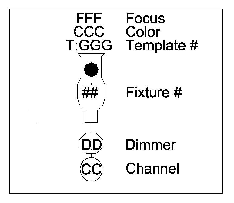
- The octagon — the icon closer to the fixture — is where we should
enter the dimmer number, which, in most modern theaters, will be the same as the circuit number. In many cases,
you will not have a drawing of the circuit distribution, or the electrician will prefer to assign circuits. In these cases,
this block should be left empty, for the electrician to fill in later.
For the sake of this project, let's assume that neither of these cases is true. Our drawing file contains a
hidden layer called, "Circuits". We reveal it just as we revealed the "Area Centers" layer at the beginning of the
tutorial. Click "Format" > "Layer..." and, when the Layers manager appears, click the dot to show the "Circuits" layer.
- Now we see that circuit #5 is right next to the fixture we've drawn, so it's an easy decision.
- Click "Draw" > "Text" > "SimpleNote"
- In the "text" box, type, "5".
- Make sure "Select in graphics area" is still selected
under "Insertion point".
- For "Angle", enter "315". Click "OK"
- Hover over the dot in the octagon and, when "Endpoint"
appears, click.
- So as not to have problems, later, with duplicates, it's a good idea to keep a list of circuits you've
already used. This is especially important in theatres in which the same circuit number appears in different
places.
- Hide the "Circuits" layer.
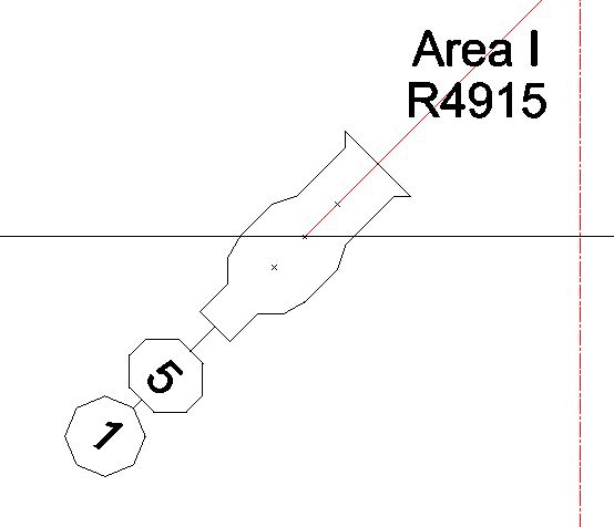
- Since this fixture will be focused on Area I, let's assign it to
channel #1. Follow the steps above to put a "1" in the circle. Now your drawing should look like this:
|
|
Drawing More Fixtures:
|
Now let's draw the other front light for Area I:
- Zoom in on the symbol for Area I.
- Click on the guide line we drew to the #2 FOH to highlight it.
- Click "Modify" > "Mirror".
- Hover over the crossed lines of the area center block until "End point" appears. Click.
- Move the mouse down the screen just a couple of inches, and click.
- Press [RETURN].
Now zoom out so you can see the entire drawing...and you see we have a problem. The end of the guide
line is far SL of the end of the hanging position, so we'll have to compromise on the angle at which
this light will strike the actor:
- Highlight the line and delete it.
- If the "Ortho" button at the bottom of your screen
is highlighted click it to toggle Ortho mode off.
- Select the "Line" tool and hover over the center of
Area I until "End point" appears. Click.
- Hover over the SL end of the #2FOH and, when "End point" appears,
click. Press [ESCAPE].
- Highlight the guide line we just drew. Right click, and select
"Properties".
- You can see that the new guide line, as shown by the bottom-most
field in the "Properties" box, is 12'-6" long. Right click and choose "Deselect All".
- Close the "Properties" box.
Since the new fixture placement is somewhat closer to the actor than that of the first light we
drew, we should recalculate, to see if a 36° Source Four is still the best choice.
Doing the same math we did before, we find that our new throw is approximately 16' (2' shorter than that
of the first light), and our field width is approximately 10'-4". This is acceptable, but the shorter throw
will make the light brighter (remember the Inverse Square Law!). Will it be too bright?
In a word...no. Doing the same math as before tells us that the intensity level will be 320 footcandles.
This seems significantly brighter than the 253 footcandles we're getting from the other fixture, but the human
eye is a funny thing. When comparing two fixtures, if one is anywhere from 50%-200% as bright as the other,
the audience will not notice any appreciable difference.
Using the same process as before, draw the second fixture, using a 45° angle instead of the 315° we used earlier.
Reveal the "Circuits" layer again, and you will see that circuit #1 is the closest to the new unit, so enter "1"
in the octagon, as before. Since this unit will also be focused on Area 1, we'll want it, like its companion,
in channel #1 as well, so enter a "1" in the circle. Label it, as with the other fixture, with its focus note
and color. This part of your drawing should now like something like this:
 Now, using the steps above, draw in the front lights for Areas 2-4.
When you've finished this, you'll note that the lights at either end of the pipe are very
close together, which would make them hard to focus without bumping into each other.
Now, using the steps above, draw in the front lights for Areas 2-4.
When you've finished this, you'll note that the lights at either end of the pipe are very
close together, which would make them hard to focus without bumping into each other.
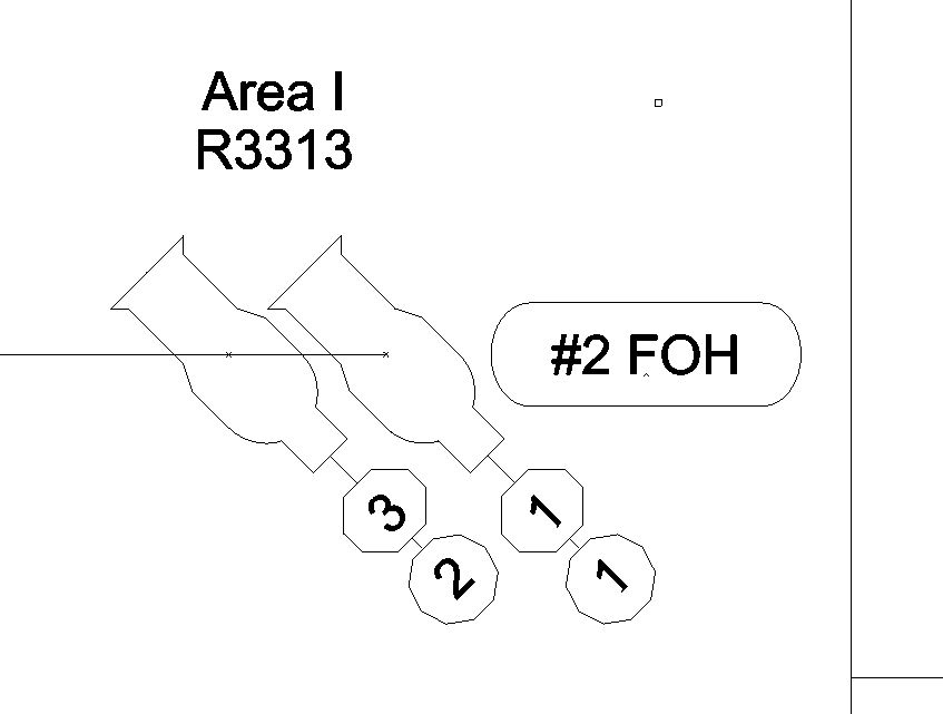 Generally, it's a good idea to keep fixtures at least 18" apart, although some designers,
including, on occasion, Jeff, use 14" centers. In this case, the lights are barely 12" apart.
To fix this:
Generally, it's a good idea to keep fixtures at least 18" apart, although some designers,
including, on occasion, Jeff, use 14" centers. In this case, the lights are barely 12" apart.
To fix this:
- Select the line tool and hover over the end of the hanging
position until "End point" appears. Click.
- Type "@1'<90"
- Click on the line you just drew, to select it. Type "move" [RETURN].
- Press [RETURN] again.
- Type "1.5'<180" [RETURN]
- Highlight all the blocks and text associated with the SR fixture.
- Type "move" [RETURN]. hover over the crossed lines in the center
of the fixture until "End point" appears. Click.
- Hover over the point at which the guide line you just drew intersects the hanging position,
until either "End point" or "Intersec" appears. Click. Delete the guide line.
- The fixture is now 18" from its neighbor. If you have not yet done so, add the text labels
for focus and color.
- Do the same for the fixtures on the other end of the pipe.
Now, the #2 FOH should look like this (If you used different circuit numbers, don't worry about it, as long as
you didn't assign the same circuit to different channels):
|
|
Twofering:
|
Now that we have our Area 1-4 front lights drawn in, let's add one more light to the #2 FOH. Let's add a
DC special:
- Put a 26° Source Four at the point at which the center line intersects
the #2 FOH, with a rotation angle of 0°. Your drawing should now look like this:
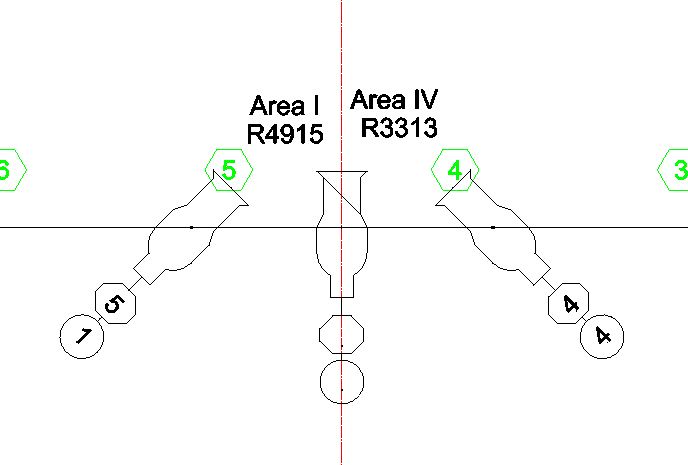
- As you can see, we don't have room for the text labels describing
focus and color, due to the labels from the features on either side, so let's fix that:
- Click to select the text reading, "Area IV".
- Right click and select "Edit".
- Under "Insertion Orientation", click the button next to "Left". (This is
a somewhat confusing menu, with four different buttons so labeled. You want the bottom-most one:
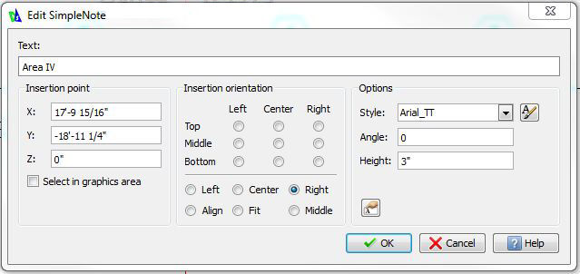 Now do the same with the text reading, "R3313".
- Now re-orient the labels for the other fixture to "Right".
- Depending on how the text was originally inserted, you still might need
to move the labels farther from center, in order to have enough room to label the new fixture:
- Make sure that the "Ortho" box, at the bottom of your screen,
is highlighted.
- Select "Area I" and "R4915". If clicking on one of these puts
you into the "Edit" screen, click, "Cancel". Then right click and select "Cancel" again.
- With the two text fields selected, type "Move" [ENTER][ENTER].
- Type "@6"<180", to move the text 6" to the left.
- If you still do not have enough room, use the same process to move, to the right,
the text for the SR fixture, substituting "0" for "180".
- Now label the fixture. Your drawing now looks like this:
 So far, we haven't used gobos (also called "templates") in any fixtures, but let's say we want one in this light.
Click "Insert" > "Block..." and choose the "Gobo" symbol. Insert it on the crossed lines in the middle of the 26°
Source Four block. To the bottom of the text which indicates the fixture's focus
and color, add "T:A MSDS-8000", meaning that we are using Apollo's "Rocky Breakup" template.
The light now looks like this:
So far, we haven't used gobos (also called "templates") in any fixtures, but let's say we want one in this light.
Click "Insert" > "Block..." and choose the "Gobo" symbol. Insert it on the crossed lines in the middle of the 26°
Source Four block. To the bottom of the text which indicates the fixture's focus
and color, add "T:A MSDS-8000", meaning that we are using Apollo's "Rocky Breakup" template.
The light now looks like this:
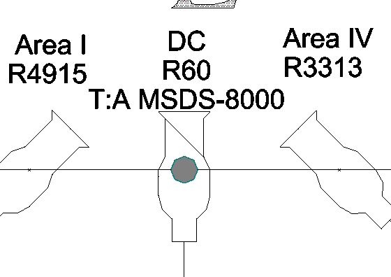 Unfortunately, the center line passes through the middle of the light, which makes the
drawing unclear and messy.
Unfortunately, the center line passes through the middle of the light, which makes the
drawing unclear and messy.
- Type "Modify" [ENTER]
- The command line instructs you to "Specify entities".
Click on the centerline at any place below the #2 FOH. Press [ENTER].
- The command line instructs you to "Specify new point".
Click on the center line at any place above the text.
Now let's move the "CL" block:
- Click on the block. Type "Move" [ENTER]
- Click on the block again.
- Raise it up to a point above the text, and click.
- Now we need to find a circuit for the new light, which is going to be complicated
by the fact that we have already used all the circuits on the #2 FOH. We could run a circuit in from
another position, but we might need those later, so let's explore another option:
- Both fixtures which are focused on Area I are assigned to channel #1. Almost
always, when fixtures are in the same channel as each other, they can be twofered so as to also be in the
same circuit/dimmer ("Almost always", because we are limited by the capacities of the dimmer, the twofer,
and the cable. In this case, we are assuming that all of these are rated at 20 Amps, which is the norm. Twenty Amps, at 120V
is 2400 Watts.)
- Select and delete the dimmer and channel information (and the "dimmer-channel" block)
for the fixture currently assigned to dimmer #5.
- Draw a 1'-3" line, at an angle of 270°, from the middle of the rear end of the same fixture.
To do this, after selecting the starting point, type, "@1'3"<270".
- Now, select and delete the dimmer and channel information (and the "dimmer-channel" block)
for the fixture currently assigned to dimmer #1.
- Draw a 1'-3" line, at an angle of 270°, from the middle of the rear end of that fixture.
- Draw a line connecting the bottom-most points of the two lines.
- Insert the "dimmer-channel" block at the left-most end of the
line you just drew, and label it as dimmer #1 and channel #1.
- Insert the "twofer" block at the left-most end of the
horizontal line. Your drawing now looks like this:
- You'll notice that the horizontal line passes through the "dimmer-channel"
block of the DC special. Let's fix that:
- Move the "channel-dimmer" block 13.25" down.
- Click "Insert" > "Block...". Select the "Arc" block and attach it to the line
at the top of the "dimmer-channel" symbol.
- Draw a line from the top of the arc to the bottom of the fixture. Your drawing should look
something like this:

- Now assign the fixture to dimmer #5 and whichever channel
you choose.
|
|
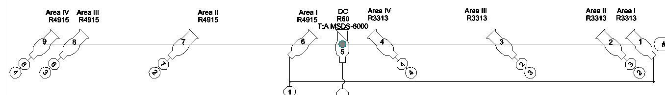
Numbering the Fixtures:
|
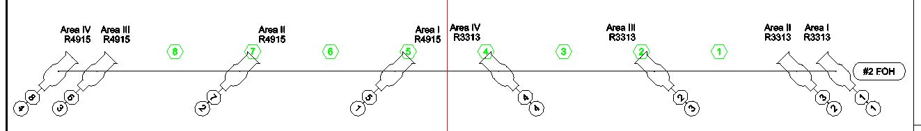
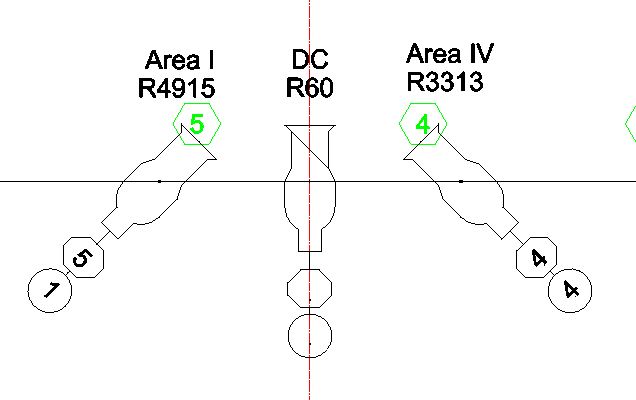
- We don't need it any more, so hide the "Circuits" layer.
Click "Format" > "Layer Tools" > "Hide Layer", and click on any of the green hexagons.
Press [RETURN].
- Starting at the SL side (Note: Some designers prefer to start
on SR. This is purely a matter of personal style. This applies to area center numbering
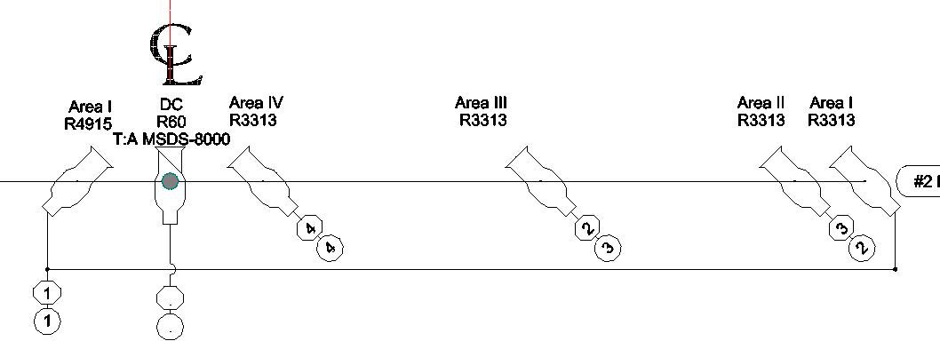
and channel assignments, as well), number the instrument sequentially. Now your drawing looks like
this:
At this point, you will want to light the rest of the stage, including actors standing on the set (and the
set itself). This tutorial has given you the tools you need to do so. If anything seems unclear, or if
you have questions, feel free to email Jeff at:
(jeff[at]jeffsalzberg.com)
|
|
Printing the Plot:
|
Even the best-drafted plot does us no good unless we can get it into the hands of
the electricians (or, in the case of this project, the hands of the instructor who
will be grading it). To print a hardcopy of the plot, click the printer icon on the
menubar. The "Print-Model" dialogue box will appear:
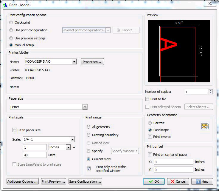 Make sure the "Manual setup", "Print on center of paper",
"Current view", and "Landscape" buttons are selected.
Our drawing is designed to be printed on a letter-sized sheet of paper at a scale of Ľ" : 1'-0",
so select "Letter" under "Paper size".
Under "Print scale", make sure that "Fit to paper size" is not checked. From the "Scale"
dropdown window, select "Ľ=1'"
Click "OK". A message will appear telling you that the printable area is bigger than your
paper size and asking you if you still want to print. Click "Yes".
Make sure the "Manual setup", "Print on center of paper",
"Current view", and "Landscape" buttons are selected.
Our drawing is designed to be printed on a letter-sized sheet of paper at a scale of Ľ" : 1'-0",
so select "Letter" under "Paper size".
Under "Print scale", make sure that "Fit to paper size" is not checked. From the "Scale"
dropdown window, select "Ľ=1'"
Click "OK". A message will appear telling you that the printable area is bigger than your
paper size and asking you if you still want to print. Click "Yes".
|
|
Export to PDF:
|
Using the "print" function is fine, as long as your plot can fit onto a letter-sized sheet of paper, but in most
cases, this will not be the case. The most commonly-used sizes for light plots are:
- "ARCH C"-sized: 18" x 24"
- "ARCH D"-sized: 24" x 36"
- "ARCH E1"-sized: 30" x 42"
- "ARCH E0"-sized: 36" x 48"
Most of us do not have printers which can accomodate paper sizes that large, so...what to do?
Fortunately, most "big box" office supply stores have copy departments which can print large-format
black-and-white drawings in Adobe's
Portable Document Format
(PDF), and most medium or large cities have big reprographics shops (or even small copy shops) which
offer the same service, faster and less expensive. Many of these also offer large format color PDF printing,
but this tends to be very costly.
To export your PDF file:
- Click "File" > "Export" > "PDF Export".
- Navigate to the target folder and either enter a file name
or press [ENTER] to accept the default.
- When the "Select sheets" dialogue box appears, make sure that
the only box checked is "Model". Click "OK".
- Select the appropriate sheet size and click "OK".
Before emailing the file to the print shop, it's always a good idea to preview it in the Acrobat
Reader. Note that, while you may usually use another PDF reader, the shop almost certainly uses
the Adobe product, so it's safer to preview your file with that application.
A more extensive Draftsight tutorial can be downloaded
here.
|
|